2012 Freightliner M2 Blower Motor Wiring Diagram
Climate Control
Cab Climate-Control Panel
Fan Control
The fan switch controls the rate that air is blown through the selected air outlets. It has 8 fan-speed settings, and an OFF position. See Fig. 7.1 . To increase the airflow, turn the switch clockwise to a higher number. To decrease the airflow, turn the switch counterclockwise to a lower number. Setting the fan switch at the OFF position disables the cab air conditioning (A/C), and sets the air source to fresh-air mode.
NOTE: When the sleeper A/C is running, even though the cab fan switch may be in the OFF position, the cab fan will operate at low speed. This is necessary to protect the evaporator in the cab HVAC system from freezing.
There is a slight delay between the time the engine is started and the blower is operational. It can take an additional 4 seconds for the blower to reach high speed. The blower motor performs a self-test immediately after the engine is started, which causes the delay.
Air Selection
The air-selection switch allows you to direct the flow of air through the face outlets, the floor outlets, the defrost (windshield) outlets, or a combination of these outlets.There are a total of 9 possible air-selection modes. See Fig. 7.2 .
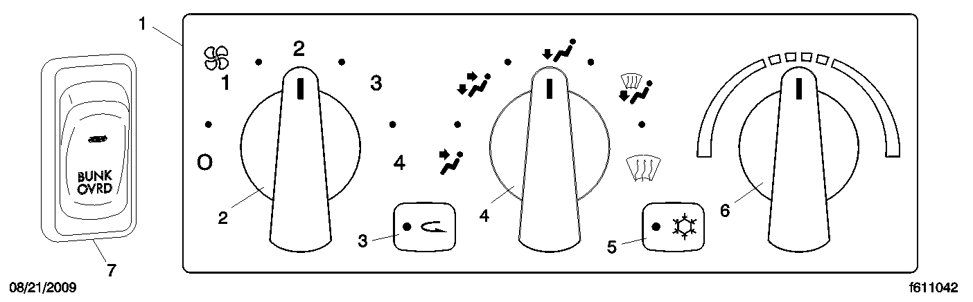
- 1. Climate-Control Panel
- 2. Fan Switch
- 3. Recirculation Button
- 4. Air-Selection Switch
- 5. Air-Conditioning Button
- 6. Temperature-Control Switch
- 7. Bunk-Override Switch
Fig. 7.1, Cab Climate-Control Panel
1.
Face Mode: Directs all airflow through the face outlets in the instrument panel.
2.
Selection between Face Mode and Bi-Level Mode: Directs 75 percent of the airflow through the face outlets, and 25 percent through the floor outlets.

- 1. Face Mode
- 2. Selection Between Face Mode and Bi-Level Mode
- 3. Bi-Level Mode
- 4. Selection Between Bi-Level Mode and Floor Mode
- 5. Floor Mode
- 6. Selection Between Floor Mode and Floor/Defog Mode
- 7. Defog Mode
- 8. Selection Between Defog Mode and Defrost Mode
- 9. Defrost Mode
Fig. 7.2, Air Selection Modes
3.
Bi-Level Mode: Directs the airflow equally to the face outlets and floor outlets.
4.
Selection between Bi-Level Mode and Floor Mode: Directs 25 percent of the airflow through the face outlets, and 75 percent through the floor outlets.
5.
Floor Mode: Directs all airflow through the floor outlets.
6.
Selection between Floor Mode and Floor/Defog Mode: Directs 75 percent of the airflow through the floor outlets, and 25 percent through the defrost outlets.
7.
Defog Mode: Directs the airflow equally to the floor outlets and the defrost outlets. The air conditioner automatically turns on in this mode. The recirculation button will not work in this mode.
8.
Selection between Defog Mode and Defrost Mode: Directs 75 percent of the airflow through the defrost outlets, and 25 percent through the floor outlets. The air conditioner automatically turns on in this mode. The recirculation button will not work in this mode.
9.
Defrost Mode: Directs all airflow through the defrost outlets. The air conditioner automatically turns on in this mode. The recirculation button will not work in this mode.
Temperature Control
The temperature-control switch is used to set the desired temperature. Turn the temperature-control switch clockwise, to the red area, for warm air. Turn the switch counterclockwise, to the blue area, for cool air.
Air Conditioning
The air conditioner cools and dehumidifies the air inside the cab. Press the air-conditioning button to turn the air conditioner ON and OFF. See Fig. 7.3 .

- 1. Amber Indicator
Fig. 7.3, Air-Conditioning Button
When the A/C is operating, the amber indicator on the air-conditioning button will be illuminated regardless of whether the request for A/C comes from the cab climate-control panel, or the sleeper climate-control panel. When the instrument panel lights are on, the snowflake indicator on the air-conditioning button will be illuminated.
The A/C will automatically disable when the outside-air temperature is low enough to make air conditioning ineffective, or conditions exist that put the HVAC system into protection mode.
Recirculation
The recirculation mode limits the amount of outside air entering the cab. It can be used to prevent dusty or smoky air from entering the cab. The recirculation mode can also decrease the time required to cool or heat the cab interior during extreme outside temperature conditions. Press the recirculation button to activate it, or cancel it. When the recirculation mode is ON, the amber indicator on the recirculation button will be illuminated. See Fig. 7.4 .

- 1. Amber Indicator
Fig. 7.4, Recirculation Button
The recirculation button will not work when the air-selection switch is in one of the following modes:
the selection between defog mode and defrost mode
NOTE: To prevent the buildup of fumes or odors, and to prevent oxygen depletion inside the cab, the system switches from full-recirculation mode to partial-recirculation mode after 20 minutes. In extremely dusty or smoky conditions, the partial-recirculation mode can be overridden by pressing the recirculation button twice to obtain full-recirculation mode. This action resets the 20-minute timer.
Bunk Override
The bunk-override switch allows the driver to remotely set the fan speed and temperature settings for the sleeper. See Fig. 7.1 .
When the override switch is not activated, adjusting the climate control in the cab does not affect the sleeper settings. Activating the bunk-override switch causes the cab controls to override the settings on the sleeper HVAC control panel, and the sleeper HVAC will mimic the cab settings. An amber LED in the switch is illuminated when the bunk-override switch is activated.
Adjusting the sleeper HVAC controls at any time, or pressing the switch, will cancel the override mode and the sleeper HVAC will be controlled by the sleeper-control panel. The amber indicator in the bunk-override switch will be off.
Sleeper Climate-Control Panel
The sleeper HVAC system features Constant Discharge Temperature Control (CDTC). The CDTC maintains a constant temperature of airflow in the sleeper regardless of outside air temperature, selected fan speed, engine coolant temperature, or engine coolant flow. Once the temperature-control switch is set to the desired temperature, no other adjustments are necessary.
Fan Control
The fan switch controls the sleeper HVAC system fan speed. It has 8 fan-speed settings, and an OFF position. To increase the airflow, turn the switch clockwise to a higher number. To decrease the airflow, turn the switch counterclockwise to a lower number. See Fig. 7.5 .

- 1. Fan Switch
- 2. Temperature-Control Switch
Fig. 7.5, Sleeper Climate-Control Panel
NOTE: When the cab A/C is on, even though the sleeper fan switch may be in the OFF position, the sleeper fan will operate at low speed. This is necessary to protect the evaporator in the sleeper HVAC system from freezing.
Temperature Control
The temperature-control switch is used to set the desired temperature in the sleeper. Turn the switch clockwise, to the red area, for warm air. Turn the switch counterclockwise, to the blue area, for cool air. The sleeper A/C automatically turns on when necessary, to maintain the selected temperature. The CDTC system is disabled when the temperature-control switch is in the maximum cool or warm positions.
Accessory Heaters
Optional accessary heaters are available from the factory in several configurations. Familiarize yourself with the equipment on your specific vehicle, and follow the manufacturer's operating and maintenance instructions.
Do not operate fuel-operated heaters in an area where flammable vapors, including gasoline or diesel fumes, are present, such as at filling stations and tank farms. Turn off a fuel-operated heater and allow it shut down completely before entering an area where flammable gases or liquids are present. Heaters continue to operate for up to three minutes after being turned off.
Failure to observe these precautions could cause an explosion or fire, resulting in serious property damage, and personal injury or death.
Parked HVAC
The Bergstrom NITE parked HVAC system consists of a compact electrical 3000-BTU air-conditioning system, and a diesel-fired heater unit. It is completely self-contained, and runs on 12-volt deep-cycle batteries located between the frame rails. The parked HVAC batteries are isolated from the vehicle-starting batteries, to prevent the starting batteries from being drawn down during HVAC operation.
The A/C system is designed to maintain cool air in the sleeper interior without having the engine running. However, the parked A/C unit will not cool down a hot sleeper that has been sitting in the sun without the vehicle A/C running. If the interior temperature is higher than desired, start the engine and run the vehicle A/C system until the desired sleeper temperature is achieved. This will help cool the sleeper to a temperature that the parked A/C system can maintain. For optimal operation, the curtain between the cab and the sleeper should be closed when using the Parked HVAC A/C system.
The A/C unit is located under the lower bunk in the sleeper compartment, and intakes air through a grille located on the front panel of the lower bunk. The outlet ducting runs from the left side of the unit to an outlet on the back wall of the sleeper.
The heater unit is located next to the A/C unit. It intakes air through a grille located on the right side of the front panel of the lower bunk. The outlet ducting runs from the back of the unit to a grille on the left side of the front panel of the lower bunk.
Do not operate fuel-operated heaters in an area where flammable vapors, including gasoline or diesel fumes, are present, such as at filling stations and tank farms. Turn off a fuel-operated heater and allow it shut down completely before entering an area where flammable gases or liquids are present. Heaters continue to operate for up to three minutes after being turned off.
Failure to observe these precautions could cause an explosion or fire, resulting in serious property damage, and personal injury or death.
IMPORTANT: Blocked vents will hamper the operation of the unit. Keep the area around the air intake grilles clear of objects that may block air flow, or emit objectionable odors into the HVAC system.
Parked-HVAC Controls
The control panel for the parked HVAC is located on the left side of the rear wall, in the sleeper. It has a temperature-control dial, and a 4-position mode switch. Turn the temperature-control dial to the left for cooling, and to the right for heat. See Fig. 7.6 . See Table 7.1 for a description of the mode functions.
After using the system, turn the mode switch to the OFF position, even if the unit is not running, or the batteries may not charge properly.

- 1. Temperature-Control Dial
- 2. Mode Switch
- 3. A/C Only
- 4. Heat Only
- 5. AUTO
- 6. OFF
Fig. 7.6, Parked-HVAC Control Panel
| Parked-HVAC Mode Operation | |
|---|---|
| Mode | Function |
| OFF | Turns the unit OFF. |
| AUTO | Allows the unit to automatically heat or cool the sleeper, depending on the temperature setting and the sleeper temperature. Adjusts the compressor, heater, and fans to keep temperature constant. |
| Heat Only | Allows only the heat portion of the system to run. Adjusts the heater only to keep the temperature constant. |
| A/C Only | Allows only the A/C portion of the system to run. Adjusts compressor and fans only to keep the temperature constant. |
Table 7.1, Parked-HVAC Mode Operation
Posted by: alexisporteee0194755.blogspot.com
Source: https://dtnacontent-dtna.prd.freightliner.com/content/public/dtna-servicelit/dtna/en_us/freightliner/drivers-manuals/122sd-and-coronado-132-drivers-manual/section_ch07dm494.html

Post a Comment for "2012 Freightliner M2 Blower Motor Wiring Diagram"